![]()
![]()
![]()
![]()
![]()
![]()
![]()
| |||
| |||
|
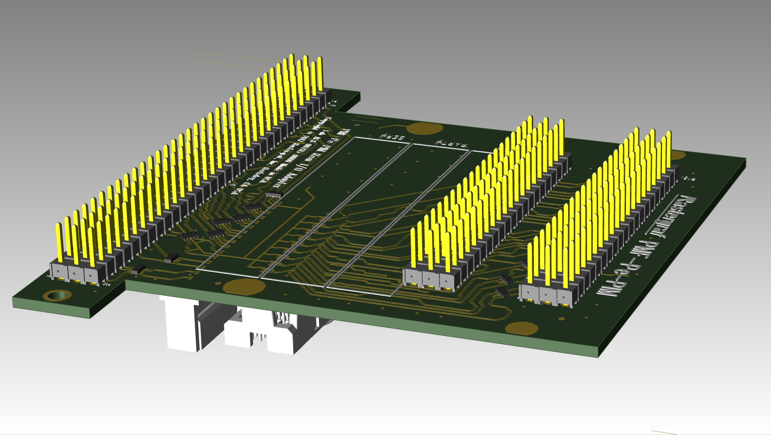
PMC/XMC Graphics Carriers | PFX-PIM General Purpose PMC I/O Module (PIM) for the PMF-E and PEX-P XMC and PMC Carriers | Available Q1 2019 Features
| ||
| ||||
| ||||
| The PFX-PIM (PMC I/O Module) is used with both the PMF-E and the PEX-P carrier boards. The PFX-PIM follows the VITA 36 - 199x Draft Standard but uses a modified board layout to accommodate all the signals: 74.0mm x 69.4 mm main (standard) board area plus added 95.0mm x 12.0 mm tab for PMC breakout. Tab area is positioned over carrier board connector but does not touch it. If necessary, tab area can be removed prior to shipping but access to Pn4 will be lost. It is used with a compatible Rear Transition Module (RTM) for VME, CompactPCI, or OpenVPX. All signals are clamped by high-speed ESD TVS protection diodes. Signal connections from XMC or PMC connector are routed to 0.1” pin array breakouts as signal pair + ground sets and are tightly matched- and equal-length routed. Pn4 sgnals are connected to a standard PMC connector and follow the VITA 46.9 "P64s" pinout, which is a misnomer because the signals are wired as differential pairs, so it is effectively "P32d". The PMC signal set is broken out on a 3 row by 64-pin pin arrays. The PMC signal traces are wired as pairs to the outer rows. The center row of pins is connected to ground. Pn6 sgnals are connected to a standard XMC connector, following the "XIM" enhancement as suggested by Extreme Engineering. They follow the VITA "X8d+X12d+X38s". Like the P64s, the X38s is also a misnomer because the signals are wired as differential pairs, so it is effectively "X19d". The XMC signal sets are broken out on two 3 row by 20-pin pin arrays. The XMC signal traces are wired as pairs to the first 2 pins in each row. The third pin is wired to ground.
| |||
| Home I Products I PMC Boards I Support I About Us I Partners I Contact Us I Legal Notice I Site Map I Search | ||||